Which Pins Are CAN High and CAN Low? OBD2 Explained
Quick Answer
On a standard OBD2 diagnostic connector, pin 6 is CAN High (CAN-H) and pin 14 is CAN Low (CAN-L). Pin 6 sits in the top row and pin 14 sits directly below it in the bottom row, when you look at the vehicle socket with its wide side up.
This is an identification guide: find the right two contacts, tell High from Low when the connector is unlabelled, and avoid the counting mistake that sends you to the wrong pin.
How to Find Pin 6 and Pin 14 in Seconds
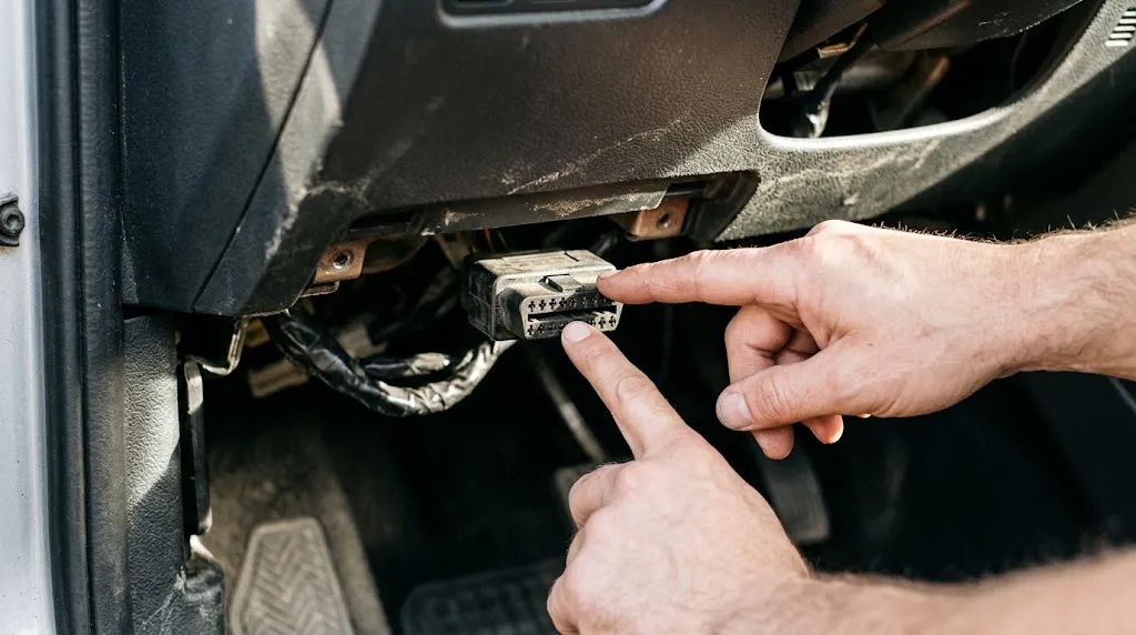
Start with the vehicle socket, the female connector under the dashboard, not the plug on a scan tool. Hold that picture in mind first, because the plug is a mirror image and is the usual source of confusion.
With the socket’s wide side up, the top row runs from pin 1 on the left to pin 8 on the right. The bottom row runs from pin 9 on the left to pin 16 on the right. Count across the top row to the sixth contact and you have pin 6. Count across the bottom row to the sixth contact and you have pin 14, because 9 is first, 10 is second, 11 is third, 12 is fourth, 13 is fifth, and 14 is sixth.
That shared sixth position is the easiest memory aid: CAN High and CAN Low form a vertical pair in the same column. If the two contacts you have chosen are not in the same column, you have miscounted, or you are looking at the connector from the wrong side.
Before probing, check for small numbers moulded into the housing or a wiring diagram for the specific vehicle, held in the same orientation as the socket.
The Neighbouring Pins That Cause Miscounts
Most miscounts happen at the edges of the pair, not in the middle of the connector. Pin 5 is signal ground and pin 7 is the K-line on older protocols. Pin 13 is manufacturer-specific and pin 15 is the L-line on older protocols. None of those is a CAN wire, but each sits close enough to pin 6 or pin 14 to cause a wrong probe if you count from the wrong end.
| Position | Pin | What it is |
|---|---|---|
| Top row, fifth | 5 | Signal ground, not CAN Low |
| Top row, sixth | 6 | CAN High |
| Top row, seventh | 7 | K-line on older protocols, not CAN High |
| Bottom row, fifth | 13 | Manufacturer-specific, not CAN Low |
| Bottom row, sixth | 14 | CAN Low |
| Bottom row, seventh | 15 | L-line on older protocols, not CAN Low |
Pin 4 is chassis ground and pin 16 is battery power. Those two matter for a different reason: they are the reference and the power supply for your checks, and they are also the pins most often confused with a data line when a tool powers up but will not communicate. A powered tool proves power and ground, not CAN. For the ground side in detail, see the guide to OBD2 ground pins, and for the power side, see whether pin 16 is always 12 volts.
How to Tell CAN High From CAN Low When Nothing Is Labelled
Counting is usually enough on a standard socket. The problem starts with a loose connector, replacement socket, breakout box, or harness where the two CAN wires look alike. Then you need a second confirmation.
Do not rely on wire colour alone. Colours vary by manufacturer, model year, and harness supplier, so colour can support an identification but cannot prove it.
The reliable distinction is direction during a dominant bit. CAN High rises while CAN Low falls. In the idle, or recessive, state, both sit near 2.5 volts to ground on a typical high-speed CAN network. When a dominant bit is sent, CAN High moves toward about 3.5 volts and CAN Low moves toward about 1.5 volts. That opposite movement is the signature of the pair, and it is why the two wires must not be treated as interchangeable.
A multimeter is a blunt tool here. It averages the rapid changes, so it will often show both lines near 2.5 volts while the bus is active. That suggests the pair is roughly alive, but it does not cleanly separate High from Low. An oscilloscope shows the direction of movement and therefore the identity. With only a multimeter, use counting and the wiring diagram as the primary identification.
Key Insight
High and Low do not mean high voltage and low voltage in the simple power sense. They describe two halves of a differential pair, and the useful signal is the difference between them.
The Texas Instruments CAN bus application note describes the same recessive and dominant levels: about 2.5 volts on both lines at rest, then about 3.5 volts on CAN High and about 1.5 volts on CAN Low when dominant, giving a typical 2-volt difference.
The Mirror-Image Trap: Socket Versus Plug
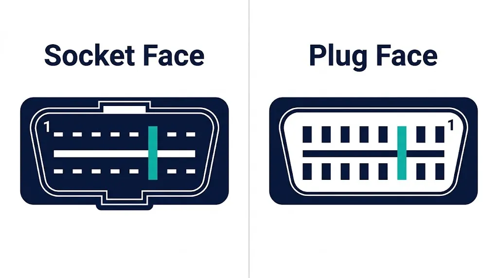
Here is the mistake that catches even careful readers. The vehicle socket and the scan tool plug are mirror images. When you turn the plug around to look at its face, pin 1 moves to the top right instead of the top left, and the whole numbering runs backwards from the socket view.
That matters when you probe the plug, build an extension, or follow a wire from the back of a connector. If you apply socket counting to a plug face, you will land on the wrong contacts. The safe habit is to state which side you are looking at before you count: socket face, plug face, or the back of the connector where the wires enter. Then count in that orientation only.
Match the wide side, row order, and ground and power pins first. If pins 4, 5, and 16 do not line up with your counting, stop and reorient before trusting pins 6 and 14.
What a Resistance Check Can and Cannot Tell You
Resistance is useful, but it answers a different question from identification. It tests termination, not identity. With the ignition off, measure between pins 6 and 14. A healthy high-speed CAN network often reads about 60 ohms, because two 120-ohm terminating resistors at the ends of the network appear in parallel at the diagnostic port.
A reading near 120 ohms suggests one terminator is not connected. A reading near zero suggests the two lines are shorted together. An open-circuit reading suggests a break or a missing connection. Each of those points to wiring or termination, but none of them tells you which of the two contacts is High and which is Low, because resistance between the pair is the same either way round.
If the reading is abnormal, check the wiring diagram and connectors next, not a replacement module based on one number.
Warning
Never jumper pins 6 and 14 together, and never apply battery voltage to either CAN pin to test it. Shorting the pair or forcing voltage onto a data line can damage control modules. Keep probes on the intended terminals only.
When Pins 6 and 14 Are Not the Answer
Pin 6 and pin 14 are the standard diagnostic CAN assignment under SAE J1962 and ISO 15765-4. That does not mean every vehicle uses them for diagnostics, and it does not mean every CAN network in the vehicle reaches the diagnostic port.
In the United States, CAN became the required OBD2 diagnostic protocol for new light-duty vehicles from model year 2008 onward. Many earlier vehicles use other pins instead: pins 7 and 15 for ISO 9141-2 or KWP2000, or pins 2 and 10 for SAE J1850. If pins 6 and 14 are empty on an older car, that may simply mean it was built for another protocol. The guide to SAE J1850 explains one of those older systems, and a vehicle OBD2 compatibility check helps confirm what your car actually supports.
A second exception is the gateway. A modern vehicle can have several internal CAN networks, and a gateway module may control which messages reach the diagnostic port. Finding pins 6 and 14 therefore proves the diagnostic pair is present, not that every module or every manufacturer-specific function is accessible through it.
A third exception is a repaired or aftermarket installation. The physical pins can be in place while the wiring behind them is wrong, so counting alone can mislead you and the wiring diagram becomes essential.
If a Scanner Will Not Connect, Check in This Order

First, confirm power and ground: does the tool power up, and do pins 16, 4, and 5 behave as expected? Second, confirm counting: are you on pins 6 and 14 in the socket orientation, not the mirrored plug orientation? Third, confirm protocol: does the vehicle actually use CAN for diagnostics?
Fourth, check the CAN pair: ignition-off resistance between pins 6 and 14, then ignition-on voltage to ground on each line. Fifth, consider the tool and gateway: a basic reader may not pass a gateway, even when the CAN pair is healthy.
For the next step after the connection itself, see how to diagnose a check engine light with OBD2.
Tip
Write down the orientation before you probe: socket or plug, wide side up or down, and which row you counted first. That one line in your notes prevents most repeat miscounts.
Related Product
CAN-Compatible OBD2 Scanner
Once pins 6 and 14 are identified, a scanner with CAN support is the practical next step for reading codes and live data on a CAN-based vehicle.
As an Amazon Associate, we earn from qualifying purchases.
Frequently Asked Questions
Are CAN High and CAN Low the same on every car brand?
For the standard OBD2 diagnostic port, yes: pin 6 is CAN High and pin 14 is CAN Low. Internal vehicle networks may use different connectors, but the diagnostic socket follows the same assignment when the vehicle uses CAN for OBD2.
Can CAN High and CAN Low be swapped?
No. Swapping them reverses the differential signal, so communication will normally fail or become corrupt. The pair must stay in its correct orientation, both at the connector and in any adapter or repaired wiring.
Why does my multimeter show about 2.5 volts on both pins?
That is the normal idle, or recessive, level for high-speed CAN, and a multimeter also averages the fast changes during communication. It does not mean the two pins are the same signal. A scope shows CAN High rising and CAN Low falling during a dominant bit.
Does a 60-ohm reading prove CAN is working?
No. It suggests termination looks normal, but it does not prove that modules are communicating, that the protocol is correct, or that a gateway will allow access. Use it with voltage checks, protocol checks, and a scan tool test.
Is CAN Low a ground wire?
No. CAN Low is a signal wire, not a ground, even though its dominant voltage is lower than the recessive level. Ground is provided by pins 4 and 5. Connecting CAN Low to ground will disrupt the differential signal.
What if one CAN wire is broken?
Communication will usually fail or become intermittent, because CAN depends on the difference between the two wires. A break, a short between the pair, or a short to power or ground is a wiring fault to trace with a diagram, not a fault to ignore because the tool sometimes connects.
Conclusion
Pin 6 is CAN High and pin 14 is CAN Low, and they sit in the same sixth column of the OBD2 socket: top row for High, bottom row for Low. Count in the socket orientation, watch out for the mirrored plug, and confirm an unlabelled pair by direction and diagram rather than by colour alone. Once the pair is identified, power, protocol, resistance, and voltage checks will tell you whether the problem is counting, wiring, or access, before any part is replaced.

I’m Alex Rahman, a car enthusiast and automotive writer focused on practical solutions, car tools, and real-world driving advice. I share simple and honest content to help everyday drivers make better decisions.
