What Are OBD2 Ground Pins? Pin 4 & Pin 5 Guide
Quick Answer
OBD2 ground pins consist of Pin 4 (Chassis Ground), which connects directly to the vehicle’s metal frame to handle high-current loads and heavy ground returns, and Pin 5 (Signal Ground), which provides a clean reference ground for sensitive electronic communication data packets. Both pins are mandatory in every standard 16-pin SAE J1962 vehicle diagnostic port to ensure stable tool power and error-free data exchange.
Understanding the OBD2 Connector and Ground Foundation
The OBD2 port is the central gateway to a vehicle’s computer network, utilizing a standardized 16-pin trapezoidal connector defined by the SAE J1962 specification. While communication lines like the CAN bus handle data transfer, the diagnostic tool cannot function safely or accurately without a reliable power foundation.
That foundation relies on three key pins: Pin 16 for battery power, along with Pin 4 and Pin 5 dedicated entirely to grounding. Separating the ground architecture into two distinct paths prevents electrical noise, voltage drops, and data corruption during live vehicle scans.
Pin 4: Chassis Ground Explained
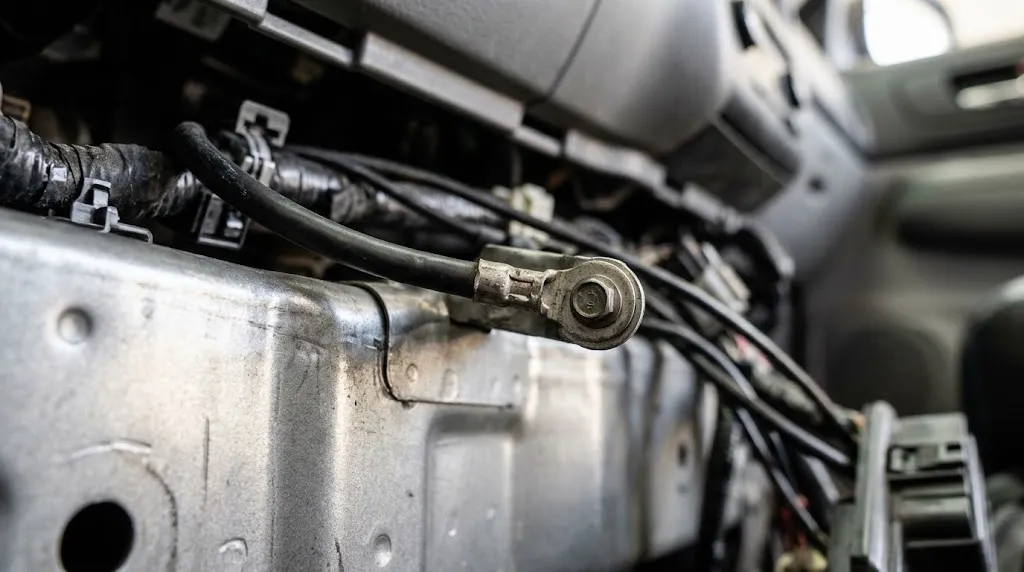
Pin 4 serves as the vehicle chassis ground. It is wired directly to the physical metal frame or body of the automobile.
Its primary purpose is to handle heavier electrical returns and complete the high-current circuit required when powering external diagnostic equipment, heavy-duty scan tools, or USB-powered interfaces plugged into the port. Because it ties directly into the vehicle’s main grounding grid, it can occasionally carry minor electrical interference from chassis accessories, blower motors, or lighting circuits.
Pin 5: Signal Ground Explained
Pin 5 functions as the signal ground (or sensor ground reference). Unlike Pin 4, it is isolated from heavy chassis currents and is tied back directly to the computer or engine control module (ECM) reference grounds.
This separation is critical for communication integrity. Sensitive data signals traveling across communication lines require a quiet, stable voltage reference point. If a scanner utilized a noisy chassis ground for data logic references, packet errors or dropped communication links would frequently occur.
Key Insight
Separating Pin 4 and Pin 5 prevents ground loops—undesirable current loops that introduce electrical noise into sensitive data streams. Maintaining low resistance across both ground pins is essential for stable OBD2 diagnostics.
Comparison of OBD2 Ground Pins
| Pin Number | Ground Type | Primary Destination | Core Function |
|---|---|---|---|
| Pin 4 | Chassis Ground | Vehicle Body / Metal Frame | Handles power return loads and hardware grounding. |
| Pin 5 | Signal Ground | ECU / Logic Reference Circuit | Provides a quiet voltage reference for clean data transmission. |
Reviewing this structural breakdown helps clarify why modern diagnostic tools require intact connections on both pins to operate reliably across various vehicle protocols.
Troubleshooting OBD2 Communication Failures Caused by Grounds
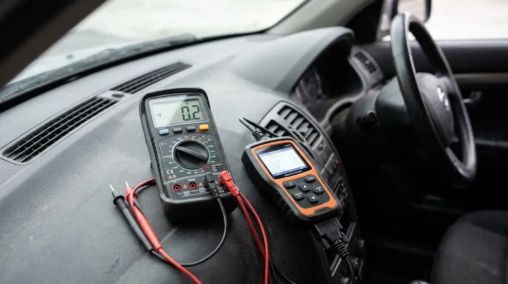
When an OBD2 scanner refuses to power on or reports a constant “Link Error,” technicians often look straight at the data lines, but faulty ground paths are a frequent culprit.
- No Power Symptoms: If Pin 16 has 12V power but the scanner remains completely dark, an open circuit on Pin 4 will often prevent the power circuit from completing its return path.
- Intermittent Dropouts: Corrosion inside the dashboard connector or a loose terminal grip on Pin 5 can corrupt data frames, causing diagnostic software to freeze or disconnect mid-session.
- Multimeter Verification: Using a digital multimeter to check continuity between Pin 4/Pin 5 and a known clean bare metal spot on the vehicle frame can quickly isolate wiring harness defects.
Warning
Never bridge Pin 4 and Pin 5 haphazardly with external high-amperage jumper wires unless testing circuit continuity under safe diagnostic conditions. Improper grounding adjustments can risk damaging sensitive vehicle control modules.
Related Product
Automotive Digital Multimeter & Circuit Tester
An essential tool for checking voltage, continuity, and ground resistance at the OBD2 port terminals.
As an Amazon Associate, we earn from qualifying purchases.
Frequently Asked Questions
Are both Pin 4 and Pin 5 required for an OBD2 scanner to work?
Yes. While some basic tools might temporarily light up with only one ground path, reliable communication across diverse vehicle networks typically requires both the chassis ground (Pin 4) and signal ground (Pin 5) to be fully active and stable.
What is the difference between chassis ground and signal ground on an OBD2 port?
Chassis ground (Pin 4) connects directly to the vehicle’s structural metal frame to handle power returns, while signal ground (Pin 5) provides an isolated, quiet reference path specifically for electronic data signals to prevent interference.
Can a bad ground pin cause a “No Communication” error?
Absolutely. If either ground pin suffers from high resistance, corrosion, or a broken wire, the scanner may either fail to turn on entirely or lose its ability to sync communication packets with the vehicle’s electronic control units.
Where is the OBD2 port located in most vehicles?
By federal and international standard mandates, the 16-pin OBD2 port must be located within two feet of the steering wheel, typically underneath the driver-side dashboard near the center console or steering column.
Can I use Pin 4 as a ground source for custom electronics?
While Pin 4 is tied to the chassis, it is generally discouraged to draw heavy operating power or major auxiliary ground loads through the diagnostic port, as this can overload the vehicle’s interior diagnostic fuse circuit.
Why do older vehicles sometimes experience ground dropouts on diagnostic ports?
Over years of exposure, moisture and physical stress can cause oxidation to form inside the port terminals or at the factory grounding points under the dashboard, creating high resistance that disrupts low-voltage signal communication.
Conclusion
Understanding the function of OBD2 ground pins—specifically the division between chassis ground (Pin 4) and signal ground (Pin 5)—is essential for effective vehicle troubleshooting. While they often go unnoticed behind the dashboard, these ground lines ensure your diagnostic tools receive clean power and maintain robust communication data loops. Proper maintenance and awareness of these pins can save considerable time when diagnosing elusive electrical or communication errors.
A. SEO Package

I’m Alex Rahman, a car enthusiast and automotive writer focused on practical solutions, car tools, and real-world driving advice. I share simple and honest content to help everyday drivers make better decisions.
