How to Identify an OBD2 Protocol: Pins and Checks Guide
Quick Answer
Identify an OBD2 protocol by checking the populated pins in the 16-pin diagnostic connector, then confirming it with a scanner. Pins 6 and 14 point to CAN, pins 2 and 10 point to J1850 PWM, pin 2 without pin 10 points to J1850 VPW, and pin 7 points to ISO 9141-2 or KWP2000. The scanner result is the confirmation, because pin 7 alone cannot separate those last two protocols.
An OBD2 protocol is the communication language a vehicle uses for standardized diagnostics. The connector shape is the same across compliant vehicles, but the language is not, so a scanner can power on and still fail to talk to a car. Use two clues: read the connector pins to narrow the possibilities, then let the scanner confirm the protocol it actually used.
Start With the Scanner, Not the Brand
For most readers, the fastest identification is a multi-protocol scanner. Plug it in, turn the ignition on, and let it try to connect. Many scanners and apps show the protocol after a successful connection, under a connection, vehicle, adapter, or information screen.
If your scanner does not show the protocol, the connection may still have succeeded. A successful read of live data or trouble codes means it found a working protocol, even if it does not name it.
Do not start from brand alone. A manufacturer can change protocols by model, year, market, and trim, so a badge narrows the likely answer but is not proof. Use brand and year as a first guess, then check pins or a scanner result.
The Five OBD2 Protocols at a Glance
Standardized OBD2 diagnostics use five main protocols. A vehicle normally uses one for its standardized OBD2 connection, although other networks in the same car may use different methods for non-OBD2 functions.
| Protocol | Standard | Key connector pins | Most associated with |
|---|---|---|---|
| CAN | ISO 15765-4 | 6 and 14 | Modern vehicles; US light-duty vehicles from model year 2008 |
| J1850 PWM | SAE J1850 | 2 and 10 | Older Ford vehicles |
| J1850 VPW | SAE J1850 | 2, without 10 | Older GM vehicles |
| ISO 9141-2 | ISO 9141-2 | 7, with 15 optional | Older European and Asian vehicles |
| KWP2000 | ISO 14230-4 | 7, with 15 optional | Older European and Asian vehicles |
That last pair is the main trap in pin identification. ISO 9141-2 and KWP2000 share the same K-line pin pattern, so a pin check can place a car in the K-line family but cannot name the exact protocol. Only a scanner connection, manual protocol setting, or reliable vehicle documentation can finish that step.
CAN is the exception on newer cars. US light-duty vehicles from model year 2008 onward use CAN for standardized OBD2 diagnostics, on pins 6 and 14. Treat that as a strong clue for the covered US light-duty case, not a universal rule for heavy-duty vehicles, motorcycles, or non-US markets.
How to Read the Connector Pins
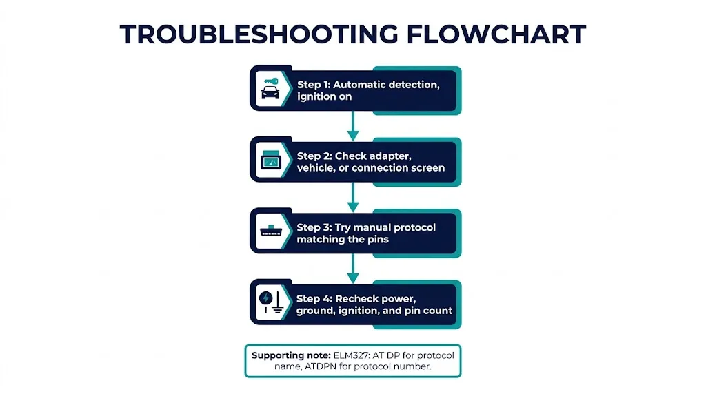
The diagnostic connector, also called the DLC, is usually under the dashboard on the driver side, but its exact position varies by model. Look for metal contacts, not just empty plastic slots: a position can exist in the housing without a wire or contact behind it.
Start with the pins present in every standardized OBD2 protocol: pin 4 for chassis ground, pin 5 for signal ground, and pin 16 for battery power. If a scanner will not power on, solve that power-and-ground problem before worrying about protocol.
Then look at the data pins:
- Pins 6 and 14: CAN High and CAN Low. Together, they point to ISO 15765-4 CAN. The CAN pins on an OBD2 connector are the pair to check first on a modern car.
- Pins 2 and 10: J1850 Bus+ and Bus-. Together, they point to J1850 PWM.
- Pin 2 without pin 10: This pattern points to J1850 VPW. Pin 10 is the deciding detail, so check it carefully before concluding VPW.
- Pin 7: The K-line. Pin 7, with pin 15 optional, points to ISO 9141-2 or ISO 14230-4 KWP2000. It does not separate those two.
Use a good light and, if needed, a photo of the socket. It is easy to miscount pins in a dark footwell, so count slowly and compare the whole pattern against the table above.
Key Insight
A single pin rarely identifies the protocol. The pattern matters: CAN needs 6 and 14, PWM needs 2 and 10, and the K-line answer stays incomplete until a scanner separates ISO 9141-2 from KWP2000.
Use Year and Market as a Clue, Not Proof
Model year helps most at the CAN boundary. If the vehicle is a US-market light-duty vehicle from 2008 or later, CAN is the expected standardized OBD2 protocol. If it is much older, the answer depends more on the manufacturer and market.
Before CAN became the standardized requirement, older Ford vehicles commonly used J1850 PWM, older GM vehicles commonly used J1850 VPW, and many older European and Asian vehicles used a K-line protocol. The SAE J1850 family covers the two North American legacy variants, so do not treat PWM and VPW as interchangeable.
European timing is different. EOBD phased in over a different period, and some vehicles adopted CAN before it became the US standardized requirement, so a European model year alone is a weaker shortcut than the US 2008 rule. In transition years, the scanner result should override a year-based guess.
Confirm the Protocol With a Scanner
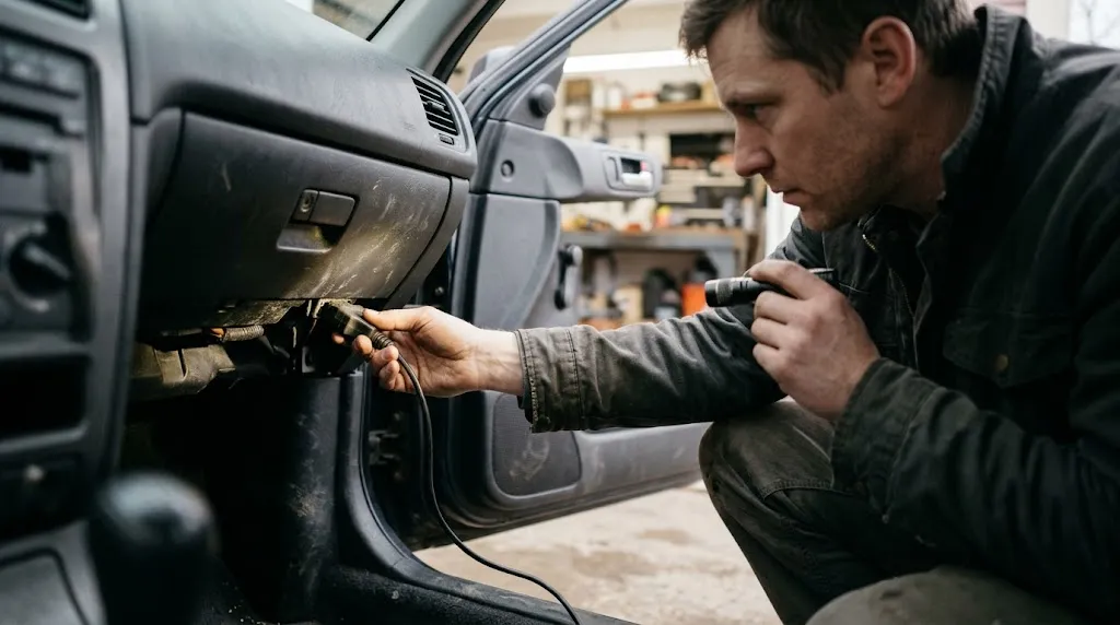
Once the pin pattern gives you a likely family, confirm it in this order:
- Set the scanner to automatic protocol detection, if it has that option, and try to connect with the ignition on.
- If it connects, check the adapter, vehicle, or connection screen for the protocol name.
- If automatic detection fails, try the manual protocol that matches your pin pattern first, rather than cycling through every option at random.
- If that manual setting also fails, recheck power, ground, ignition state, and the pin count before assuming the adapter is at fault.
For ELM327-style adapters, the protocol can also be reported through a terminal or advanced app screen. The ELM327 developer guide describes AT DP as the command that describes the current protocol, even when automatic detection normally does not report it. A related command, ATDPN, returns the protocol as a number instead of a name.
When an app shows only a number, the common ELM327 numbers are: 1 for J1850 PWM, 2 for J1850 VPW, 3 for ISO 9141-2, 4 for KWP2000 with slow initialization, 5 for KWP2000 with fast initialization, 6 for CAN 11-bit at 500 kbit/s, 7 for CAN 29-bit at 500 kbit/s, 8 for CAN 11-bit at 250 kbit/s, and 9 for CAN 29-bit at 250 kbit/s. Protocol 0 normally means automatic detection. If a number conflicts with the pin pattern and a successful connection, trust the connection that returns real data.
An ELM327 OBD2 adapter is only one route to this answer. A handheld scanner may say protocol, bus type, or communication settings, but the logic is the same: automatic first, then the manual setting that matches the pins.
Tip
Write down the confirmed protocol, model year, and market. Next time, you can go straight to the manual setting instead of repeating the pin check.
When the Clues Disagree
Disagreement usually has a mundane cause. A connector can carry more than one pin group: CAN pins for one network and K-line or J1850 wiring for another purpose, while its standardized OBD2 connection uses only one of them. The protocol that connects and returns OBD2 data is the answer for OBD2 purposes.
Another common cause is an adapter that supports only part of the protocol range. Some low-cost adapters handle CAN well but struggle with older K-line or J1850 protocols, so a failed connection can look like a vehicle problem when it is an adapter limit. If the pins point to a legacy protocol and a CAN-only adapter cannot connect, try an adapter that explicitly supports that protocol.
Manufacturer-assigned pins add a third complication. Pins 1, 3, 8, 9, 11, 12, and 13 are not assigned to a single standardized OBD2 protocol like pins 2, 6, 7, 10, and 14, so their presence should not override the main data-pin pattern.
If the clues still conflict, recheck ignition state, plug seating, socket damage, and the power feed to pin 16. A poor physical connection can make automatic detection fail even when the protocol is otherwise clear.
Warning
Do not short connector pins to test a guess, and do not force a damaged plug into the socket. A short or bent pin can turn a simple check into a wiring repair. If the socket looks damaged or the scanner has no power, stop and check power, ground, and damage first.
Mistakes That Lead to the Wrong Protocol
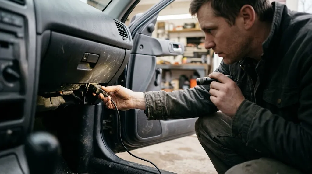
The most frequent mistake is counting an empty slot as a pin. Always look for a metal contact and, where possible, a wire behind it. A second mistake is treating a K-line result as a final answer: pin 7 narrows the field but does not choose between ISO 9141-2 and KWP2000.
A third mistake is assuming that a successful CAN connection means every system uses CAN. It means the standardized OBD2 connection used CAN; manufacturer-specific systems can still use other networks.
Finally, do not choose an adapter based only on the word universal. That can mean it supports the common protocols, but it does not guarantee every legacy protocol, CAN speed, or manufacturer-specific function. Check the supported protocol list against the pattern you found.
Related Product
OBD2 Scanner With Automatic Protocol Detection
A multi-protocol scanner that tries the likely protocols automatically makes confirmation faster, especially on an older car where the legacy protocol is still unclear.
As an Amazon Associate, we earn from qualifying purchases.
Frequently Asked Questions
Can I identify an OBD2 protocol from the car brand alone?
No, not reliably. Brand gives a likely starting point, but model, year, market, and trim can change the protocol. Use brand as a guess, then confirm with the pins or a scanner connection.
Why does my connector have pins for more than one protocol?
A vehicle can carry wiring for more than one network, while its standardized OBD2 connection uses one protocol. The protocol that connects and returns OBD2 data is the relevant answer.
What if pin 7 is present but the scanner will not connect?
Recheck ignition, plug seating, power, and ground first, then try ISO 9141-2 and KWP2000 one at a time. If neither works, the adapter may lack K-line support, or the socket or wiring may have a fault.
Does a 2008 or newer car always use CAN for OBD2?
For US-market light-duty vehicles from model year 2008 onward, CAN is the expected standardized OBD2 protocol. That does not settle every heavy-duty vehicle, motorcycle, or non-US market on its own.
How do I find the protocol if my scanner app has no protocol screen?
Check the adapter, connection, vehicle, or information screens, since wording varies. With an ELM327-style adapter, an advanced or terminal screen may report it with AT DP or ATDPN. If no screen shows it, a successful connection still proves a working protocol.
Is ISO 9141-2 the same as KWP2000?
No. They are separate protocols that share the K-line pin pattern, so pin 7 alone cannot distinguish them. Confirm the exact protocol with a scanner setting, adapter report, or reliable vehicle documentation.
Conclusion
Identifying an OBD2 protocol is a two-step check, not a single guess. Read the populated pins to narrow the field, then confirm with a scanner. Pins 6 and 14 point to CAN, pins 2 and 10 to J1850 PWM, pin 2 without pin 10 to J1850 VPW, and pin 7 to the K-line family. Only a scanner setting or adapter report can separate ISO 9141-2 from KWP2000, so keep the confirmed protocol with the vehicle details. That record also helps you pick a compatible adapter next time.

I’m Alex Rahman, a car enthusiast and automotive writer focused on practical solutions, car tools, and real-world driving advice. I share simple and honest content to help everyday drivers make better decisions.
