Can OBD2 Diagnose a Throttle Position Sensor?
Quick Answer
OBD2 can diagnose a throttle position sensor partially. It can set TPS-related trouble codes, show live throttle-position data, and record freeze-frame conditions. It cannot prove that the sensor is mechanically worn, that a connector is intermittently losing contact, or that a signal dropout is faster than the scan tool can display. Treat OBD2 as strong circumstantial evidence, not a replacement for a voltage or scope test.
A throttle position sensor is simple in concept and awkward in practice. It reports how far the throttle plate has moved, and the powertrain control module uses that report for fueling, shifting, idle control, and electronic throttle strategy. When the report looks wrong, OBD2 is often the first tool that points to the problem.
The useful question is not whether OBD2 can “diagnose” a TPS in a single step. It is what OBD2 can prove, what it can only suggest, and what still requires a meter or an oscilloscope.
What OBD2 Can and Cannot Tell You About a Throttle Position Sensor
OBD2 is good at two things: catching electrical faults that fall outside the PCM’s expected range, and showing whether the throttle-position signal behaves plausibly while the engine runs.
It is not a mechanical inspection. A sensor can wear a resistive track, develop a dead spot, or lose contact only under vibration and still produce a signal that looks acceptable during a slow scan-tool sweep. OBD2 sees what the PCM reports, not what a lab scope would see at the sensor terminals.
That distinction matters because throttle-position faults often begin as intermittent glitches. A basic scan tool may refresh the throttle PID slowly enough to miss a short dropout. The PCM may catch the dropout and set a code, or it may not, depending on how long the fault lasts and how the manufacturer programmed the monitor.
OBD2 is therefore best used as a triage tool. It tells you where to look and whether the PCM already suspects the circuit. It does not close the case by itself.
How OBD2 Actually Monitors the Throttle Position Sensor
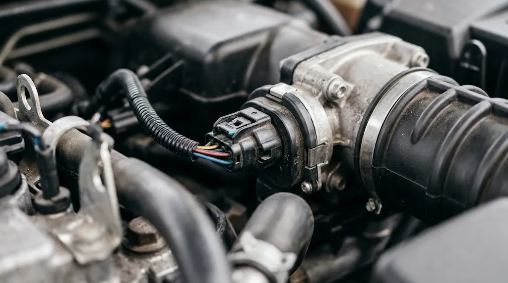
On most vehicles, the PCM supplies a 5-volt reference and a low-reference ground to the throttle position sensor. The sensor returns a signal voltage that changes with throttle angle. The PCM converts that voltage into a percentage or a calculated position value and broadcasts it over the diagnostic link.
Generic OBD2 includes a throttle-position PID, commonly known as PID 0x11. It is usually reported as a percentage from closed throttle to wide-open throttle. Many vehicles also broadcast absolute throttle position, relative throttle position, accelerator-pedal position, and commanded throttle position. These values are related, but they are not interchangeable.
A scan tool that displays only one generic throttle PID is still useful, but it may not show the same signal the PCM uses for its most sensitive rationality checks. Factory-level data often includes separate TPS 1 and TPS 2 voltages, especially on drive-by-wire vehicles. If you are serious about diagnosing an intermittent TPS fault, read the live-data guide for your tool and confirm which parameter you are actually watching.
For a step-by-step walkthrough of connecting a scanner and selecting live parameters, see how to read OBD2 live data. The process is straightforward, but the parameter choice and the way you move the throttle determine whether the test is meaningful.
The Trouble Codes That Point to a TPS Problem
Throttle-position codes are grouped around circuit voltage, range performance, and correlation between redundant sensors. The exact definitions vary by manufacturer, but the generic families are consistent.
| Code | Typical meaning | What it suggests |
|---|---|---|
| P0120 | Throttle position sensor/switch A circuit malfunction | A general circuit fault; the PCM cannot trust the signal |
| P0121 | TPS A circuit range/performance | The signal is present but does not match expected throttle angle or RPM |
| P0122 / P0123 | TPS A circuit low / high voltage | The signal is outside the normal voltage range |
| P0222 / P0223 | TPS B circuit low / high voltage | The second sensor in a redundant system is out of range |
| P2135 | TPS 1 and 2 correlation | Two sensors disagree beyond the allowed margin |
P0121 is often the most misleading code for a DIY diagnosis. It does not automatically mean the sensor is bad. The AutoZone explanation of P0121 notes that the PCM compares the TPS signal with RPM and expects the two to agree. A damaged wire harness, a poor ground, or a sensor with an internal short can all produce the same complaint.
P2135 is a correlation code. On drive-by-wire vehicles, the throttle body usually contains two position sensors that move in opposite directions. One sensor’s voltage rises as the throttle opens while the other falls. If the PCM sees them disagree beyond a small percentage, it sets a correlation fault and may enter reduced-power mode. That code is strong evidence that something in the throttle assembly or its wiring is inconsistent, but it still does not tell you whether the fault is inside the sensor, the connector, or the harness.
How to Use Live Data to Judge a Throttle Position Sensor
A live-data test is more informative than reading codes alone, but only if you perform it deliberately. A quick blip of the throttle proves very little.
- Connect the scanner and select the correct throttle parameters. If the tool offers TPS 1 and TPS 2 voltage, watch both. If it offers only a percentage, watch that value and compare it with accelerator-pedal position.
- Turn the ignition on with the engine off. This gives a stable electrical baseline without engine vibration or idle-control corrections.
- Press the accelerator slowly from closed to wide open and back. The throttle-position value should change smoothly and progressively. It should not jump, flat-spot, or drop to zero in the middle of the sweep.
- Repeat the sweep several times. A fault that appears only once every five sweeps is still a fault. Watch for inconsistency between passes.
- Compare related parameters. Throttle position, accelerator-pedal position, engine RPM, and calculated load should move in a coherent direction. If throttle position rises while RPM and load do not follow, the signal is suspect.
The scan tool’s refresh rate matters here. A slow tool can make a ragged signal look smooth because it samples only a few times per second. The limitations of OBD2 live-data accuracy are worth understanding before you condemn a sensor based on a single graph. Trend and smoothness are more trustworthy than one snapshot value.
If the vehicle has a stored code, check freeze-frame data before clearing anything. Freeze frame records the conditions present when the fault set, including throttle position, engine speed, load, and temperature. A TPS code that sets only at a specific throttle angle or only when the engine is hot is more likely to be a sensor or connector fault than a blanket wiring failure.
What a Scan Tool Can Miss
A scan tool sees the PCM’s interpretation of the signal. That leaves several blind spots.
Fast intermittent dropouts. A sensor can lose contact for a few milliseconds as the throttle passes a worn spot on its resistive track. The PCM may catch the glitch and set a code, but the scan tool may never display it because the sample rate is too slow. An oscilloscope is the tool that exposes this kind of fault.
Wiring resistance under load or vibration. A connector can test fine at rest and fail when the engine moves or the harness flexes. A live-data sweep with the engine idling and the harness wiggled can sometimes reveal the problem, but a voltage-drop test at the sensor terminals is more direct.
Mechanical wear inside the sensor. A worn resistive track can produce a signal that looks smooth during a slow hand sweep but breaks up under vibration or rapid movement. The PCM may not set a code until the fault becomes frequent enough to fail a rationality monitor.
PCM substitution strategies. Some systems use one TPS signal as a backup when the other is implausible. The scan tool may show a plausible value while the faulty signal is being ignored. Manufacturer-specific data and bidirectional controls are often needed to see what the PCM is actually doing.
When a Scan Tool Diagnosis Is Not Enough

OBD2 becomes insufficient when the evidence is ambiguous. A smooth live-data graph with a recurring P0121 is a classic example. The sensor may be fine, and the real fault may be a poor connection, a damaged ground, or a reference voltage that drops under load.
At that point, move to direct electrical testing. Measure the 5-volt reference and ground at the sensor connector with the key on. Back-probe the signal wire and watch the voltage as you sweep the throttle. A digital multimeter with a min/max function can catch short dropouts that a display cannot show in real time. If the vehicle uses two TPS sensors, verify that their voltages move in opposite directions as the throttle opens and close.
Factory service information is useful because it gives the expected voltage range and the exact correlation margin for that platform. The Mitchell1 SureTrack real-fix example shows how a technician used live data, a lab scope, and a visual inspection together to trace an erratic throttle signal to an internal throttle-body fault. The scan tool pointed to the area; the scope and meter proved the cause.
Some repairs also require a scan tool with bidirectional controls or a relearn function. Cleaning a throttle body or replacing a sensor can change the learned closed-throttle value. If the vehicle idles high or the throttle feels different afterward, the fix may be incomplete until the adaptation is reset or a relearn procedure is performed.
What to Do After the Scan Tool Gives You an Answer
Use the scan tool to narrow the fault, then verify before replacing parts. A practical sequence looks like this:
- Record all stored, pending, and permanent codes, plus freeze-frame data.
- Inspect the throttle body connector, pins, and harness for corrosion, looseness, or chafing.
- Run a slow throttle sweep in live data and watch for smoothness and consistency.
- Check reference voltage, ground, and signal voltage at the sensor with a meter.
- Wiggle the harness while watching live data or meter readings to expose intermittent faults.
- Use a scope if the signal is erratic but the meter looks normal.
- After repair, clear codes, perform any required relearn, and verify with a road test.
Replacing a throttle body or sensor because a code points in that direction is a guess, not a diagnosis. The better use of OBD2 is to decide which electrical test to perform next. That is where the tool earns its place.
Related Product
OBD2 scanner with live-data graphing
A scanner that can graph throttle-position data makes it easier to see whether the signal moves smoothly as you press the pedal. It does not replace a scope for fast glitches, but it is a practical first step.
As an Amazon Associate, we earn from qualifying purchases.
Frequently Asked Questions
Can a cheap OBD2 scanner diagnose a throttle position sensor?
A basic scanner can read TPS-related trouble codes and may show a throttle-position PID. That is enough to start the diagnosis, but it is not enough to confirm the sensor is faulty. Cheap tools often lack fast live-data graphing, manufacturer-specific TPS voltages, and bidirectional tests. Use the code as a lead, not a verdict.
What should throttle position read at idle and full throttle?
Generic OBD2 often reports throttle position as a percentage, with closed throttle near the low end and wide-open throttle near the high end. The exact numbers vary by vehicle and by the PID selected. Absolute, relative, and commanded throttle position are different parameters. A smooth progressive change matters more than a specific percentage.
Can a throttle position sensor fail without setting a code?
Yes. A sensor can develop a dead spot or an intermittent dropout that the PCM does not detect often enough to set a code. The vehicle may hesitate, surge, or shift poorly while no fault is stored. Live-data graphing and a scope test are more likely to expose this kind of failure than a code reader alone.
Does a throttle position sensor need to be reprogrammed after replacement?
Many vehicles require a throttle relearn or adaptation after the throttle body or sensor is replaced or cleaned. The procedure may be as simple as an idle relearn or as involved as a bidirectional scan-tool routine. Check the service information for the specific vehicle. If the idle is high or the throttle feels off after repair, the relearn may not have completed.
Can OBD2 tell the difference between a bad TPS and a bad throttle body?
Not reliably. On drive-by-wire vehicles, the TPS is often integrated into the throttle body, and a correlation code can come from the sensor, the internal electronics, the connector, or the wiring. OBD2 can show that the signal is implausible, but it usually cannot isolate the failed component without voltage, resistance, or scope testing.
Is it safe to drive with a throttle position sensor code?
It depends on the symptom and the vehicle’s response. A stored code with normal drivability is less urgent than a code accompanied by reduced power, limp mode, or an erratic throttle. Because throttle faults affect power delivery, have the circuit tested promptly. If the vehicle enters limp mode or the throttle behaves unpredictably, avoid highway driving until it is repaired.
Conclusion
OBD2 is a useful first step for a throttle position sensor complaint, but it is not a complete diagnosis. It can flag a code, show a live PID, and preserve the conditions that triggered the fault. It cannot see every dropout, measure resistance under vibration, or prove that the sensor is mechanically worn.
The practical approach is to let the scan tool narrow the circuit, then verify with a meter, a wiggle test, or a scope before replacing parts. A smooth live-data graph with a recurring code is a signal to test the wiring, not to condemn the sensor. Used that way, OBD2 saves time without pretending to be more than it is.

I’m Alex Rahman, a car enthusiast and automotive writer focused on practical solutions, car tools, and real-world driving advice. I share simple and honest content to help everyday drivers make better decisions.
