What Is ISO 9141 OBD2? Protocol Overview & Pinout Guide
Quick Answer
ISO 9141 is an international standard for automotive diagnostic systems, specifically defining the communication protocol used between a vehicle’s On-Board Diagnostics (OBD) system and external scan tools. In an OBD-II context, ISO 9141 (often designated as ISO 9141-2) acts as one of the primary legacy signaling protocols—using a single bidirectional K-line and an optional L-line—to transmit diagnostic trouble codes, sensor data, and real-time vehicle parameters from the engine control unit (ECU) to a diagnostic scanner.
What Is the ISO 9141 Protocol in Automotive Diagnostics?
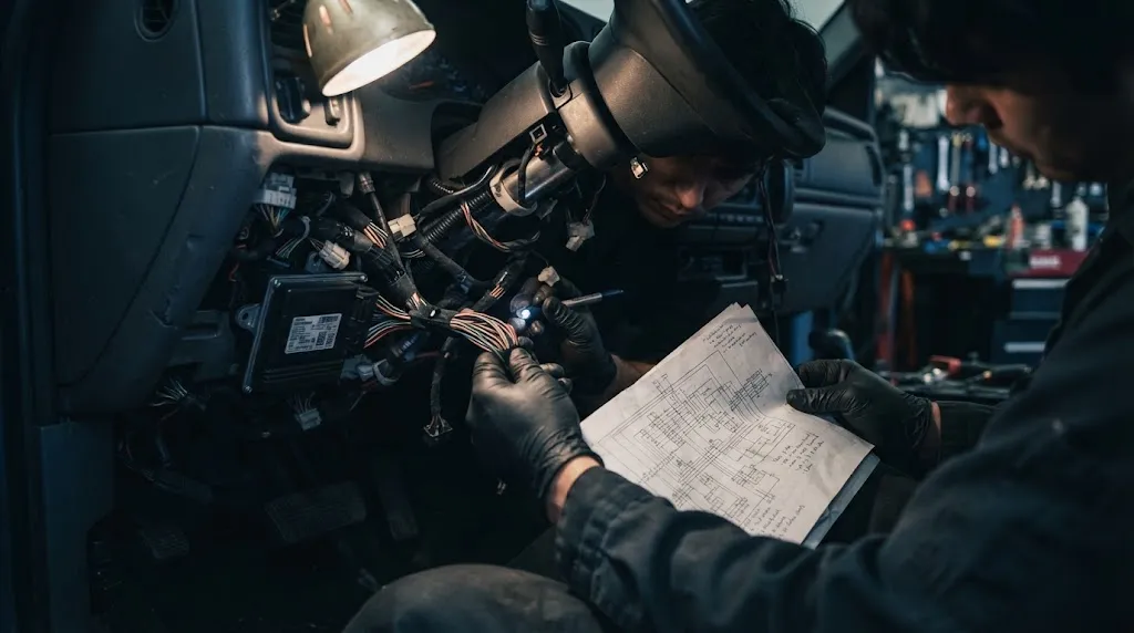
Modern vehicles rely heavily on computer networks to monitor emissions, engine performance, and electrical subsystems. The On-Board Diagnostics version 2 (OBD-II) mandate required standardized access points and communication protocols so that generic scanners could interface with any compliant vehicle.
The ISO 9141 standard specifies how diagnostic data travels across the vehicle wiring harness. Specifically, ISO 9141-2 was tailored for passenger cars, establishing voltage thresholds, timing parameters, and bit rates for serial communication. While newer protocols like Controller Area Network (CAN) have largely replaced it in modern manufacturing, ISO 9141 remains common in many vehicles produced from the late 1990s through the mid-2000s, particularly among Asian and European imports.
How ISO 9141 Communication Works
Unlike high-speed digital networks that use multiple differential data wires, ISO 9141 operates on a asynchronous serial communication scheme utilizing distinct physical lines within the standard 16-pin OBD-II port located under the vehicle dashboard.
Tip
If you are troubleshooting a communication link error with an older scan tool, verifying that your scanner supports legacy serial protocols like ISO 9141-2 is often the first step toward establishing a successful connection.
The K-Line and L-Line Architecture
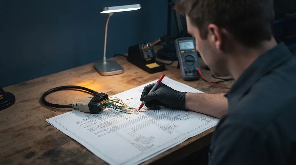
The backbone of the ISO 9141 protocol consists of two primary lines:
- The K-Line (Pin 7): This is the mandatory bidirectional data line responsible for transmitting diagnostic commands from the scan tool and returning data streams or diagnostic trouble codes from the vehicle’s ECU.
- The L-Line (Pin 15): This is an optional unidirectional line used primarily during the initialization phase to wake up or signal the ECU before data transmission shifts entirely to the K-Line. Many modern implementations operate using only the K-Line, designating them as ISO 9141-2 systems.
Communication occurs at a relatively slow default baud rate—typically 10,480 baud—using a 12-volt signaling format where data bits are pulled low against a pull-up resistor. This simplicity made it cost-effective and reliable for early automotive microcontrollers.
Pinout Configuration on the OBD-II Connector
Under the Society of Automotive Engineers (SAE) J1962 specification, the standard 16-pin diagnostic link connector (DLC) assigns specific physical pins to accommodate various global protocols. For vehicles utilizing ISO 9141, specific pins must be populated for a scan tool to interface correctly.

I’m Alex Rahman, a car enthusiast and automotive writer focused on practical solutions, car tools, and real-world driving advice. I share simple and honest content to help everyday drivers make better decisions.
